- Published at
LAB 11 - VLAN (Virtual LAN) [Device by device procedures]
![LAB 11 - VLAN (Virtual LAN) [Device by device procedures]](https://storage.mwn99.com/network_lab/lab11_cover.png)
LAB 11 - VLAN (Virtual LAN) [Device by device procedures]
Table of Contents
- Full Lab Procedures
- Equipment list
- LAB 11 - VLAN (Virtual LAN)
- Part I: Single-Switch VLANs
- Topology
- 1. Setting up topology
- 2. Set up the network topology as shown in LAB11 Part I Topology.
- 3. Start Wireshark at all hosts.
- 4. Ping a few packets
- 5. Configuration at S1.
- 6. Clear the ARP caches in all the hosts.
- 7. Repeat Steps 3 and 4.
- Part II: Multi-switch VLANs
- 1. Set up the network topology.
- 2. Clear the ARP caches in all the PCs by using
- 3. Start Wireshark at PC1, PC2, PC3, PC4 with display filter ‘arp or icmp’
- 4. Ping a few packets.
- 5. Setting up multiple VLANs:
- 6. Repeat Steps 2 - 4.
- 7. Inter-VLAN Routing with Router-on-a-Stick:
- 8. Ping from PC1 to PC4.
- Device-by-Device Lab10 SNMP Procedures
- PART I: Single-Switch VLANs
- Topology
- 1. PC1 (and S1 Console) Procedure
- 2. PC2 Procedure
- 3. PC3 Procedure
- 4. PC4 Procedure
- PART II: Multi-switch VLANs and Router-on-a-Stick
- Topology
- 1. PC1 (and S1 Console) Procedure
- 2. PC2 (and S2 Console) Procedure
- 3. PC3 (and R1 Console) Procedure
- 4. PC4 Procedure
Full Lab Procedures
Equipment list
Equipment Quantity Linux PC with one Ethernet port 4 Ethernet cable 6 USB-to-mini-USB console cable 3 Cisco switch 2 Cisco router 1
LAB 11 - VLAN (Virtual LAN)
Part I: Single-Switch VLANs
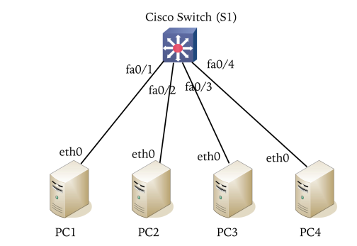
Topology
1. Setting up topology
- Connect an Rpi computer to the console port of the Cisco switch S1 in LAB11 Part I Topology.
- Open Kermit to access the switch.
(/root/) C-Kermit> set line /dev/ttyUSB0
(/root/) C-Kermit> set carrier-watch off
(/root/) C-Kermit> connect- Next,delete an existing VLAN configuration in S1 with
S1# show flash:
S1# delete vlan.dat
2. Set up the network topology as shown in LAB11 Part I Topology.
- (a) Connect four RPi computers to the Cisco switch. Use the network address 10.0.5.0/24 and assign valid IP addresses to the RPi interfaces.
- (b) Clear the ARP caches in all the computers. Use arp -a and then arp -d ipaddr where ipaddr is an IP address shown in the output of arp -a.
3. Start Wireshark at all hosts.
- capture traffic on eth0 on all hosts. Set the display filter to ‘arp or icmp’.
4. Ping a few packets
- Ping from PC1 to PC2, from PC3 to PC4, and from PC2 to PC3. Then, stop and save the Wireshark captures.
5. Configuration at S1.
- Configure the ports connected to PC1 and PC2 as one VLAN (vlan id 102), and the ports connected to PC3 and PC4 as another VLAN (vlan id 103).
- Save the VLAN configuration in the switch to a file.
S1# conf t
S1(config)# vlan 102
S1(config-vlan)# vlan 103
S1(config-vlan)# exit
S1(config)# int range fa0/1-2
S1(config-if-range)# switchport mode access        # Set fa1,2 to non-trunking layer-2 port
S1(config-if-range)# switchport access vlan 102    # Assign fa1,2 to vlan 102
S1(config-if-range)# int range fa0/3-4
S1(config-if-range)# switchport mode access
S1(config-if-range)# switchport access vlan 103
S1(config-if-range)# end
S1# show vlan
6. Clear the ARP caches in all the hosts.
7. Repeat Steps 3 and 4.
Part II: Multi-switch VLANs
1. Set up the network topology.
- Setting up the topology as shown in LAB11 Part II #1 Topology.
- (a) Delete existing VLAN database in S1 and S2 and reload by using
# delete vlan.dat
# write erase
# reload- Answer ’no’ when being asked to save the current configurations.
- (b) Assign IP addresses in the range 10.0.1.0/24 to four interfaces of PC1, PC2, PC3, and PC4.
2. Clear the ARP caches in all the PCs by using
basharp -a
and then
basharp -d ipaddr
to delete the cache of IP address ipaddr.
Alternatively, use baship -s neigh flush all
3. Start Wireshark at PC1, PC2, PC3, PC4 with display filter ‘arp or icmp’
4. Ping a few packets.
- Ping from PC1 to PC2, PC1 to PC3, PC2 to PC3, and PC2 to PC4. Stop and save the traffic captures.
5. Setting up multiple VLANs:
- (a) Configure the ports of Cisco switches S1 and S2 in LAB11 Part II #1 Topology, such that PC1 and PC3 are in one VLAN (vlan id 11), PC2 and PC4 are in another VLAN (vlan id 22).
- After the configuration, ping to verify that PCs in the same VLAN can communicate.
- At S1 and S2,
S1(config)# vlan 11
S1(config-vlan)# vlan 22
S1(config-vlan)# exit
S1(config)# int fa0/1
S1(config-if)# switchport mode access
S1(config-if)# switchport access vlan 11
S1(config-if)# int fa0/2
S1(config-if)# switchport mode access
S1(config-if)# switchport access vlan 22
S1(config-if)# int fa0/3
S1(config-if)# switchport mode trunk
S1(config-if)# switchport trunk allowed vlan all
S1(config-if)# end
S1# show vlan
S1# show int trunk- (b) Save the VLAN configurations of S1 and S2 to files.
6. Repeat Steps 2 - 4.
7. Inter-VLAN Routing with Router-on-a-Stick:
- (a) From LAB11 Part II #1 Topology, connect Cisco Router R1 to Switch S2 to obtain the topology in LAB11 Part II #2 Topology
- (b) Reassign IP addresses of PC1 and PC3 to 10.0.11.11/24 and 10.0.11.13/24, and IP addresses of PC2 and PC4 to 10.0.22.12/24 and 10.0.11.14/24.
- (c) Configure fa0/4 of S2 as trunk port
S2(config)# int fa0/4
S2(config-if)# switchport mode trunk
S2(config-if)# switchport trunk allowed vlan all
S2(config-if)# end
S2# show vlan
S2# show interfaces trunk- (d) Create two subinterfaces g0/0.1 and g0/0.2 at R1 to route VLAN traffic. Assign g0/0.1 with IP address 10.0.11.1/24 and g0/0.2 with IP address 10.0.22.1/24.
R1(config)# int g0/0.1
R1(config-subif)# encapsulation dot1Q 11               # Add this subinterface to VLAN 11
R1(config-subif)# ip address 10.0.11.1 255.255.255.0   # Assign IP address to g0/0.1
R1(config-subif)# int g0/0.2
R1(config-subif)# encapsulation dot1Q 22               # Add this subinterface to VLAN 22
R1(config-subif)# ip address 10.0.22.1 255.255.255.0   # Assign IP address to g0/0.2
R1(config-subif)# exit
R1(config)# int g0/0
R1(config-if)# no shutdown
R1(config-if)# end
R1# show vlans                                         # Show VLANs of subinterfaces
R1# show vlan-switch
R1# show int trunk- (e) Add an appropriate default gateway to PC1, PC2, PC3, PC4. Their default gateway should be
one of the subinterface IP addresses your have configured in the previous step.
- At PC1 and PC3,
route add default gw 10.0.11.1- At PC2 and PC4,
route add default gw 10.0.22.18. Ping from PC1 to PC4.
- to verify the connectivity across VLANs. At PC2, run traceroute to PC4 and save the output.
Device-by-Device Lab10 SNMP Procedures
PART I: Single-Switch VLANs
Topology
- Switch S1: Central switch connecting all 4 PCs.
- PC1, PC2, PC3, PC4: Connect to S1 on ports
fa0/1,fa0/2,fa0/3, andfa0/4respectively. Network10.0.5.0/24.
1. PC1 (and S1 Console) Procedure
Step 1.1: Connect your console cable to Switch S1. Wipe the existing VLAN database:
(/root/) C-Kermit> set line /dev/ttyUSB0
(/root/) C-Kermit> set carrier-watch off
(/root/) C-Kermit> connect

S1# show flash:
S1# delete vlan.dat
(Restart the switch if necessary to clear the active VLANs).
Step 1.2: Configure your eth0 interface with IP 10.0.5.1/24 and clear your ARP cache:
ifconfig eth0 10.0.5.1/24 up
ip -s neigh flush all
[WAIT FOR STEP 2.1, 3.1, 4.1] Wait for PC2, PC3, and PC4 to assign their IPs and clear their ARP caches.
Step 1.3: Start Wireshark on eth0 with the display filter arp or icmp.
Step 1.4: Ping PC2 (10.0.5.2). Stop and save your Wireshark capture.
[WAIT FOR STEP 2.3, 3.3] Wait for PC2 and PC3 to finish their pings.
Step 1.5: Configure S1 to place the ports into VLAN 102 and VLAN 103:
S1# conf t
S1(config)# vlan 102
S1(config-vlan)# vlan 103
S1(config-vlan)# exit
S1(config)# int range fa0/1-2
S1(config-if-range)# switchport mode access
S1(config-if-range)# switchport access vlan 102
S1(config-if-range)# int range fa0/3-4
S1(config-if-range)# switchport mode access
S1(config-if-range)# switchport access vlan 103
S1(config-if-range)# end
S1# show vlan
S1# copy run start
[WAIT FOR STEP 2.4, 3.4, 4.2] Inform the group the VLANs are active. Wait for everyone to clear their ARP caches again.
Step 1.6: Start Wireshark again, clear your ARP cache (ip -s neigh flush all), and attempt to ping PC2 again. Note the results.
2. PC2 Procedure
Step 2.1: Configure your eth0 interface with IP 10.0.5.2/24 and clear your ARP cache:
ifconfig eth0 10.0.5.2/24 up
ip -s neigh flush all
[WAIT FOR STEP 1.2, 3.1, 4.1] Wait for the group to finish setting their IPs.
Step 2.2: Start Wireshark on eth0 with the display filter arp or icmp.
Step 2.3: Wait for PC1 to ping you. Then, ping PC3 (10.0.5.3). Stop and save your Wireshark capture.
[WAIT FOR STEP 1.5] Wait for PC1 to finish configuring VLAN 102 and 103 on Switch S1.
Step 2.4: Clear your ARP cache (ip -s neigh flush all). Start Wireshark and attempt to ping PC3 again. Note the results.
3. PC3 Procedure
Step 3.1: Configure your eth0 interface with IP 10.0.5.3/24 and clear your ARP cache:
ifconfig eth0 10.0.5.3/24 up
ip -s neigh flush all
[WAIT FOR STEP 1.2, 2.1, 4.1] Wait for the group to finish setting their IPs.
Step 3.2: Start Wireshark on eth0 with the display filter arp or icmp.
Step 3.3: Wait for PC2 to ping you. Then, ping PC4 (10.0.5.4). Stop and save your Wireshark capture.
[WAIT FOR STEP 1.5] Wait for PC1 to finish configuring the VLANs on Switch S1.
Step 3.4: Clear your ARP cache (ip -s neigh flush all). Start Wireshark and attempt to ping PC4 again. Note the results.
4. PC4 Procedure
Step 4.1: Configure your eth0 interface with IP 10.0.5.4/24 and clear your ARP cache:
ifconfig eth0 10.0.5.4/24 up
ip -s neigh flush all
[WAIT FOR STEP 1.2, 2.1, 3.1] Wait for the group to finish setting their IPs.
[WAIT FOR STEP 3.3] Start Wireshark and stand by while PC3 pings you.
[WAIT FOR STEP 1.5] Wait for PC1 to finish configuring the VLANs on Switch S1.
Step 4.2: Clear your ARP cache (ip -s neigh flush all) and observe the network behavior.
PART II: Multi-switch VLANs and Router-on-a-Stick
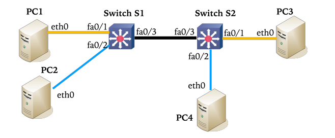
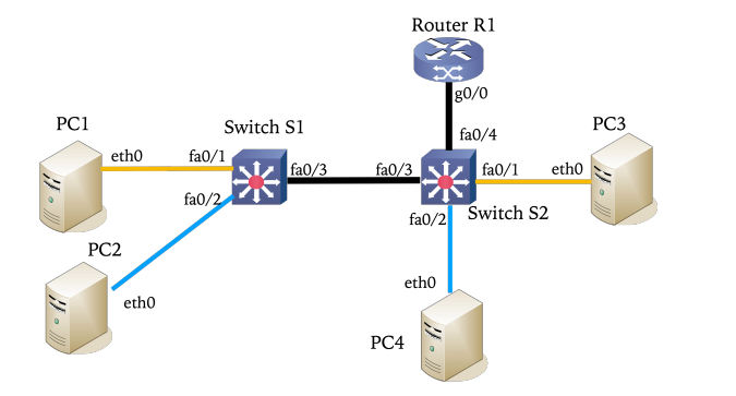
Topology
- Switch S1 & S2: Connected via a trunk link (
fa0/3on both). - PC1 & PC2: Connect to S1 (
fa0/1andfa0/2). - PC3 & PC4: Connect to S2 (
fa0/1andfa0/2).
- Router R1: Added to the topology, connecting its
g0/0interface to S2’sfa0/4interface to act as the Inter-VLAN router.
1. PC1 (and S1 Console) Procedure
Step 1.1: Rearrange the cables to match the “LAB11 Part II #1 Topology”. Ensure S1 fa0/3 connects to S2 fa0/3.
Step 1.2: On the S1 Console, wipe the configuration and VLAN database:
S1# delete vlan.dat
S1# write erase
S1# reload
(Answer ‘no’ to saving current configurations).
Step 1.3: Re-assign your IP to 10.0.1.1/24 and clear ARP:
ifconfig eth0 10.0.1.1/24 up
ip -s neigh flush all
[WAIT FOR STEP 2.3, 3.2, 4.2] Wait for all PCs to set their
10.0.1.xIPs and clear ARP.
Step 1.4: Start Wireshark (arp or icmp). Ping PC2 (10.0.1.2) and PC3 (10.0.1.3). Stop and save captures.
[WAIT FOR STEP 2.5] Wait for PC2 to finish their pings.
Step 1.5: Configure S1 for VLAN 11 (PC1), VLAN 22 (PC2), and establish the trunk to S2:
S1(config)# vlan 11
S1(config-vlan)# vlan 22
S1(config-vlan)# exit
S1(config)# int fa0/1
S1(config-if)# switchport mode access
S1(config-if)# switchport access vlan 11
S1(config-if)# int fa0/2
S1(config-if)# switchport mode access
S1(config-if)# switchport access vlan 22
S1(config-if)# int fa0/3
S1(config-if)# switchport mode trunk
S1(config-if)# switchport trunk allowed vlan all
S1(config-if)# end
S1# show vlan
S1# show int trunk
S1# copy run start
[WAIT FOR STEP 2.6] Wait for PC2 to configure S2.
Step 1.6: Ping PC3 to verify intra-VLAN communication across the trunk.
Step 1.7 (Router-on-a-Stick Prep): Connect Router R1 to S2 as shown in Topology #2. Re-assign your IP and set the default gateway for VLAN 11:
ifconfig eth0 10.0.11.11/24 up
route add default gw 10.0.11.1
[WAIT FOR STEP 3.5] Wait for PC3 to configure the Router (R1) subinterfaces.
Step 1.8: Ping PC4 (10.0.22.14) to verify Inter-VLAN routing is working.
2. PC2 (and S2 Console) Procedure
Step 2.1: Move your console cable to Switch S2.
Step 2.2: On the S2 Console, wipe the configuration and VLAN database:
S2# delete vlan.dat
S2# write erase
S2# reload
Step 2.3: Re-assign your IP to 10.0.1.2/24 and clear ARP:
ifconfig eth0 10.0.1.2/24 up
ip -s neigh flush all
[WAIT FOR STEP 1.3, 3.2, 4.2] Wait for all PCs to set their
10.0.1.xIPs.
Step 2.4: Start Wireshark.
Step 2.5: Ping PC3 (10.0.1.3) and PC4 (10.0.1.4). Stop and save captures.
[WAIT FOR STEP 1.5] Wait for PC1 to finish configuring S1.
Step 2.6: Configure S2 for VLAN 11 (PC3), VLAN 22 (PC4), and establish the trunk to S1:
S2(config)# vlan 11
S2(config-vlan)# vlan 22
S2(config-vlan)# exit
S2(config)# int fa0/1
S2(config-if)# switchport mode access
S2(config-if)# switchport access vlan 11
S2(config-if)# int fa0/2
S2(config-if)# switchport mode access
S2(config-if)# switchport access vlan 22
S2(config-if)# int fa0/3
S2(config-if)# switchport mode trunk
S2(config-if)# switchport trunk allowed vlan all
S2(config-if)# end
S2# copy run start
Step 2.7: Ping PC4 to verify intra-VLAN communication.
Step 2.8 (Router-on-a-Stick Prep): Ensure Router R1 (g0/0) is connected to S2 (fa0/4). Configure the trunk port on S2 for the router:
S2(config)# int fa0/4
S2(config-if)# switchport mode trunk
S2(config-if)# switchport trunk allowed vlan all
S2(config-if)# end
Step 2.9: Re-assign your IP and set the default gateway for VLAN 22:
ifconfig eth0 10.0.22.12/24 up
route add default gw 10.0.22.1
[WAIT FOR STEP 3.5] Wait for PC3 to configure the Router (R1) subinterfaces.
Step 2.10: Run a traceroute to PC4 (10.0.22.14) and save the output.
3. PC3 (and R1 Console) Procedure
Step 3.1: Connect your console cable to Router R1.
Step 3.2: Re-assign your IP to 10.0.1.3/24 and clear ARP:
ifconfig eth0 10.0.1.3/24 up
ip -s neigh flush all
[WAIT FOR STEP 1.3, 2.3, 4.2] Wait for all PCs to set their
10.0.1.xIPs.
[WAIT FOR STEP 1.4, 2.5] Start Wireshark and stand by while PC1 and PC2 perform pings.
[WAIT FOR STEP 1.5, 2.6] Stand by while PC1 and PC2 configure the switches.
Step 3.3: Re-assign your IP and set the default gateway for VLAN 11:
ifconfig eth0 10.0.11.13/24 up
route add default gw 10.0.11.1
Step 3.4: Wait for PC2 to configure the trunk port on S2 (fa0/4) (Step 2.8).
Step 3.5: Configure R1’s subinterfaces to handle Inter-VLAN routing (Router-on-a-Stick):
R1# conf t
R1(config)# int g0/0.1
R1(config-subif)# encapsulation dot1Q 11
R1(config-subif)# ip address 10.0.11.1 255.255.255.0
R1(config-subif)# int g0/0.2
R1(config-subif)# encapsulation dot1Q 22
R1(config-subif)# ip address 10.0.22.1 255.255.255.0
R1(config-subif)# exit
R1(config)# int g0/0
R1(config-if)# no shutdown
R1(config-if)# end
R1# show ip route
[WAIT FOR STEP 1.8, 2.10] Inform the group the router is ready. Stand by while PC1 pings and PC2 traceroutes.
4. PC4 Procedure
Step 4.1: Ensure your network cable is connected to S2 fa0/2.
Step 4.2: Re-assign your IP to 10.0.1.4/24 and clear ARP:
ifconfig eth0 10.0.1.4/24 up
ip -s neigh flush all
[WAIT FOR STEP 1.3, 2.3, 3.2] Wait for all PCs to set their
10.0.1.xIPs.
[WAIT FOR STEP 2.5] Start Wireshark and stand by while PC2 pings you.
[WAIT FOR STEP 1.5, 2.6] Stand by while PC1 and PC2 configure the switches.
Step 4.3: Re-assign your IP and set the default gateway for VLAN 22:
ifconfig eth0 10.0.22.14/24 up
route add default gw 10.0.22.1
[WAIT FOR STEP 3.5] Stand by while PC3 configures Router R1. Wait to receive cross-VLAN pings from PC1 and PC2.