- Published at
LAB 12 - Multi-Segment Network and Spanning Tree Protocol [Device by device procedures]
![LAB 12 - Multi-Segment Network and Spanning Tree Protocol [Device by device procedures]](https://storage.mwn99.com/network_lab/lab12_cover.jpg)
LAB 12 - Multi-Segment Network and Spanning Tree Protocol [Device by device procedures]
Table of Contents
- Full Lab Procedures
- Equipment list
- Topology Description (LAB 12)
- LAB 12 - STP
- Part I: Forwarding Loop
- 1. Create the network topology.
- 2. Configure the IP address of PC1 and PC2 and clear their ARP cache.
- 3. Start Wireshark on PC1 and PC2.
- 4. Type the following commands but do not press Enter:
- 5. Connect the S1-S3 and S4-S3 cables.
- Part II: Forwarding Loop
- 1. Continuing from the topology from the last step of Part I.
- 2. Reconnect the cable between S1 and S3.
- 3. Ping a few packets from PC1 to PC2.
- 4. The tree stabilizes when each switch has all its interfaces in either Blocking or Forwarding.
- 5. Save the output screenshots.
- Topology Description (LAB 12)
- PART I: Forwarding Loop
- 1. PC1 (PC1 & Switch S2 Console)
- 2. PC2 (PC2 & Switch S3 Console)
- 3. PC3 (Switch S1 Console)
- 4. PC4 (Switch S4 / Cisco Router Console)
- PART II: Spanning Tree Protocol (STP)
- 1. PC1 (PC1 & Switch S2 Console)
- 2. PC2 (PC2 & Switch S3 Console)
- 3. PC3 (Switch S1 Console)
- 4. PC4 (Switch S4 / Cisco Router Console)
Full Lab Procedures
Equipment list
Equipment Quantity Linux PC with one Ethernet interface 2 Ethernet cable 6 Cisco router 1 Cisco switch 3
Topology Description (LAB 12)
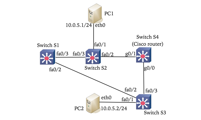
- PC1: Connects to Switch S2 via
fa0/1. IP:10.0.5.1/24. - PC2: Connects to Switch S3 via
fa0/1. IP:10.0.5.2/24. - Switch S1: Connects to S2 via
fa0/3and S3 viafa0/2. - Switch S2: Connects to PC1 via
fa0/1, S1 viafa0/3, and S4 viafa0/2. - Switch S3: Connects to PC2 via
fa0/1, S1 viafa0/2, and S4 viafa0/3. - Switch S4 (Cisco Router): Acts as a bridge. Connects to S2 via
g0/1and S3 viag0/0.
LAB 12 - STP
Part I: Forwarding Loop
1. Create the network topology.
- Connect Ethernet cables as shown in LAB 12 Topology but leave fa0/2 and fa0/3 of S3 unplugged.
- (a) Configure g0/0 and g0/1 of Cisco 2900 Router as Switch S4. Open Kermit to access the router:
(/root/) C-Kermit> set line /dev/ttyACM0
(/root/) C-Kermit> set carrier-watch off
(/root/) C-Kermit> connect- Then, enter the following commands:
Router> en
Router# conf t
Router(config)# no ip routing
Router(config)# no cdp run
Router(config)# bridge 1 protocol ieee
Router(config)# bridge 1 priority 128
Router(config)# int range g0/0-1
Router(config-if-range)# no keepalive
Router(config-if-range)# bridge-group 1
Router(config-if-range)# bridge-group 1 spanning-disabled
Router(config-if-range)# no shutdown
Router(config-if-range)# end
Router# clear bridge
Router# clear arp-cache
Router# clear mac-address-table- (b) Disable the spanning tree protocol and clear the MAC forwarding tables in Switches S1, S2, S3.
- Open Kermit to access the switch:
(/root/) C-Kermit> set line /dev/ttyUSB0
(/root/) C-Kermit> set carrier-watch off
(/root/) C-Kermit> connect- Then, enter the following commands:
SW> en
SW# conf t
SW(config)# no spanning-tree vlan 1-1014
SW(config)# mac address-table aging-time 600    # (Entries cached for 600s)
SW(config)# exit
SW# show spanning-tree
SW# clear mac address-table dynamic
2. Configure the IP address of PC1 and PC2 and clear their ARP cache.
- At PC1:
ifconfig eth0 10.0.5.1/24 up
ip -s neigh flush all- At PC2:
ifconfig eth0 10.0.5.2/24 up
ip -s neigh flush all
3. Start Wireshark on PC1 and PC2.
- Start Wireshark on PC1 and PC2 to capture traffic over interface eth0 with display filter ‘icmp’
4. Type the following commands but do not press Enter:
- At Switches S1, S2, S3
SW# show mac address-table dynamic- At Switch S4 (Cisco router)
SW# show bridge5. Connect the S1-S3 and S4-S3 cables.
- Connect the S1-S3 and S4-S3 cables (fa0/2 and fa0/3 of S3) and wait a few seconds to let the links established.
- Ping a few packets from PC1 to PC2.
- Now you should the LEDs at the switch ports blinking really fast.
- At all the switches,
- press Enter to run the commands you have entered in Step 4 to display the MAC forwarding tables.
- Save the MAC forwarding tables of all the switches.
- Disconnect the S1-S3 cable and wait 10 seconds.
- Then, ping a few packets from PC1 to PC2. Save the MAC forwarding tables of all the switches.
Part II: Forwarding Loop
1. Continuing from the topology from the last step of Part I.
- enable the spanning tree protocol and clear the forwarding tables in all the switches.
- (a) At Switches S1,S2,S3 (Cisco switches), execute the following commands.
SW(config)# spanning-tree vlan 1-1014
SW(config)# exit
SW# clear mac address-table dynamic
SW# show spanning-tree- (b) At Switch S4 (Cisco router), execute the following commands:
Router(config)# no ip routing
Router(config)# no cdp run
Router(config)# spanning-tree vlan 1        # (Enable ga0/0, ga0/1 to send BPDU).
Router(config)# bridge 1 protocol ieee
Router(config)# bridge 1 priority 128
Router(config)# int range g0/0-1
Router(config-if-range)# no keepalive
Router(config-if-range)# bridge-group 1
Router(config-if-range)# no bridge-group 1 spanning-disabled
Router(config-if-range)# no shutdown
Router(config-if-range)# end
Router# clear bridge
Router# clear arp-cache
Router# clear mac-address-table
Router# show bridge
Router# show spanning-tree
2. Reconnect the cable between S1 and S3.
- Wait about 10 seconds to let the spanning tree stabilize.
3. Ping a few packets from PC1 to PC2.
4. The tree stabilizes when each switch has all its interfaces in either Blocking or Forwarding.
Check the tree status at each switch by using the command:
SW# show spanning-tree5. Save the output screenshots.
Topology Description (LAB 12)
- PC1: Connects to Switch S2 via
fa0/1. IP:10.0.5.1/24. - PC2: Connects to Switch S3 via
fa0/1. IP:10.0.5.2/24. - Switch S1: Connects to S2 via
fa0/3and S3 viafa0/2. - Switch S2: Connects to PC1 via
fa0/1, S1 viafa0/3, and S4 viafa0/2. - Switch S3: Connects to PC2 via
fa0/1, S1 viafa0/2, and S4 viafa0/3. - Switch S4 (Cisco Router): Acts as a bridge. Connects to S2 via
g0/1and S3 viag0/0.
PART I: Forwarding Loop
1. PC1 (PC1 & Switch S2 Console)
Step 1.1: Connect PC1’s Ethernet port to S2 fa0/1. Connect S2 fa0/3 to S1 fa0/3. Connect S2 fa0/2 to S4 g0/1.
Step 1.2: Open the Kermit terminal to S2. Disable the spanning tree protocol and clear the MAC tables:
(/root/) C-Kermit> set line /dev/ttyUSB0
(/root/) C-Kermit> set carrier-watch off
(/root/) C-Kermit> connect

SW> en
SW# conf t
SW(config)# no spanning-tree vlan 1-1014
SW(config)# mac address-table aging-time 600
SW(config)# exit
SW# show spanning-tree
SW# clear mac address-table dynamic
Step 1.3: On PC1, configure the IP address and clear the ARP cache:
ifconfig eth0 10.0.5.1/24 up
ip -s neigh flush all
[WAIT FOR STEP 2.3, 3.2, 4.2] Wait for the other workstations to finish their initial setups and clear their tables.
Step 1.4: Start Wireshark on PC1 to capture traffic over interface eth0 with the display filter icmp.
Step 1.5: On the S2 console, type the following command but DO NOT press Enter yet:
SW# show mac address-table dynamic[WAIT FOR STEP 2.5] Wait for Workstation 2 to connect the final cables to S3.
Step 1.6: Ping a few packets from PC1 to PC2. You should see the LEDs at the switch ports blinking very fast (Broadcast Storm).
[WAIT FOR STEP 2.6, 3.4, 4.4] Inform the other workstations that the ping is active so they can execute their held commands.
Step 1.7: Press Enter on your S2 console to run the command you typed in Step 1.5. Save the MAC forwarding table.
[WAIT FOR STEP 2.7] Wait for Workstation 2 to disconnect the S1-S3 cable.
Step 1.8: Ping a few packets from PC1 to PC2 again.
Step 1.9: Run show mac address-table dynamic on S2 again and save the MAC forwarding table.
2. PC2 (PC2 & Switch S3 Console)
Step 2.1: Connect PC2’s Ethernet port to S3 fa0/1. DO NOT connect S3 to S1 or S4 yet (leave fa0/2 and fa0/3 unplugged).
Step 2.2: Open the Kermit terminal to S3. Disable the spanning tree protocol and clear the MAC tables:
(/root/) C-Kermit> set line /dev/ttyUSB0
(/root/) C-Kermit> set carrier-watch off
(/root/) C-Kermit> connect

SW> en
SW# conf t
SW(config)# no spanning-tree vlan 1-1014
SW(config)# mac address-table aging-time 600
SW(config)# exit
SW# show spanning-tree
SW# clear mac address-table dynamic
Step 2.3: On PC2, configure the IP address and clear the ARP cache:
ifconfig eth0 10.0.5.2/24 up
ip -s neigh flush all
[WAIT FOR STEP 1.3, 3.2, 4.2] Wait for the other workstations to finish their initial setups.
Step 2.4: Start Wireshark on PC2 to capture traffic over interface eth0 with the display filter icmp. Type the following command on the S3 console but DO NOT press Enter yet:
SW# show mac address-table dynamic[WAIT FOR STEP 1.5, 3.3, 4.3] Wait until all other workstations have typed their
showcommands and are holding.
Step 2.5: Connect the S1-S3 cable (fa0/2) and S4-S3 cable (fa0/3). Wait a few seconds to let the links establish.
[WAIT FOR STEP 1.6] Tell Workstation 1 they can now ping PC2. Watch for the broadcast storm.
Step 2.6: Press Enter on your S3 console to run the command you typed in Step 2.4. Save the MAC forwarding table.
Step 2.7: Disconnect the S1-S3 cable (from fa0/2) and wait 10 seconds.
[WAIT FOR STEP 1.8] Tell Workstation 1 they can now ping PC2 again.
Step 2.8: Run show mac address-table dynamic on S3 again and save the MAC forwarding table.
3. PC3 (Switch S1 Console)
Step 3.1: Connect S1 fa0/3 to S2 fa0/3. (S1 fa0/2 will be connected by Workstation 2 later).
Step 3.2: Open the Kermit terminal to S1. Disable the spanning tree protocol and clear the MAC tables:
(/root/) C-Kermit> set line /dev/ttyUSB0
(/root/) C-Kermit> set carrier-watch off
(/root/) C-Kermit> connect

SW> en
SW# conf t
SW(config)# no spanning-tree vlan 1-1014
SW(config)# mac address-table aging-time 600
SW(config)# exit
SW# show spanning-tree
SW# clear mac address-table dynamic
[WAIT FOR STEP 1.3, 2.3, 4.2] Wait for the other workstations to finish their initial setups.
Step 3.3: Type the following command on the S1 console but DO NOT press Enter yet:
SW# show mac address-table dynamic[WAIT FOR STEP 2.5] Wait for Workstation 2 to connect the cables to S3.
[WAIT FOR STEP 1.6] Wait for Workstation 1 to initiate the ping.
Step 3.4: Press Enter on your S1 console to run the command you typed. Save the MAC forwarding table.
[WAIT FOR STEP 2.7] Wait for Workstation 2 to disconnect the S1-S3 cable.
[WAIT FOR STEP 1.8] Wait for Workstation 1 to initiate the second ping.
Step 3.5: Run show mac address-table dynamic on S1 again and save the MAC forwarding table.
4. PC4 (Switch S4 / Cisco Router Console)
Step 4.1: Connect S4 g0/1 to S2 fa0/2. (S4 g0/0 will be connected by Workstation 2 later).
Step 4.2: Open the Kermit terminal to S4. Configure the bridge protocol, disable spanning tree, and clear the tables:
(/root/) C-Kermit> set line /dev/ttyACM0
(/root/) C-Kermit> set carrier-watch off
(/root/) C-Kermit> connect

Router> en
Router# conf t
Router(config)# no ip routing
Router(config)# no cdp run
Router(config)# bridge 1 protocol ieee
Router(config)# bridge 1 priority 128
Router(config)# int range g0/0-1
Router(config-if-range)# no keepalive
Router(config-if-range)# bridge-group 1
Router(config-if-range)# bridge-group 1 spanning-disabled
Router(config-if-range)# no shutdown
Router(config-if-range)# end
Router# clear bridge
Router# clear arp-cache
Router# clear mac-address-table
[WAIT FOR STEP 1.3, 2.3, 3.2] Wait for the other workstations to finish their initial setups.
Step 4.3: Type the following command on the S4 console but DO NOT press Enter yet:
Router# show bridge[WAIT FOR STEP 2.5] Wait for Workstation 2 to connect the cables to S3.
[WAIT FOR STEP 1.6] Wait for Workstation 1 to initiate the ping.
Step 4.4: Press Enter on your S4 console to run the command you typed. Save the bridge forwarding table.
[WAIT FOR STEP 2.7] Wait for Workstation 2 to disconnect the S1-S3 cable.
[WAIT FOR STEP 1.8] Wait for Workstation 1 to initiate the second ping.
Step 4.5: Run show bridge on S4 again and save the forwarding table.
PART II: Spanning Tree Protocol (STP)
1. PC1 (PC1 & Switch S2 Console)
Step 1.1: Continuing from Part I, enable the spanning tree protocol and clear the forwarding table on S2:
SW(config)# spanning-tree vlan 1-1014
SW(config)# exit
SW# clear mac address-table dynamic
SW# show spanning-tree
[WAIT FOR STEP 2.1, 3.1, 4.1] Wait for the other workstations to enable STP on their respective switches.
[WAIT FOR STEP 2.2] Wait for Workstation 2 to reconnect the S1-S3 cable and for the tree to stabilize (approx 10-30 seconds).
Step 1.2: Ping a few packets from PC1 to PC2.
Step 1.3: Check the tree status on S2. Verify interfaces are in Blocking or Forwarding states, and save the output screenshot:
SW# show spanning-tree2. PC2 (PC2 & Switch S3 Console)
Step 2.1: Enable the spanning tree protocol and clear the forwarding table on S3:
SW(config)# spanning-tree vlan 1-1014
SW(config)# exit
SW# clear mac address-table dynamic
SW# show spanning-tree
[WAIT FOR STEP 1.1, 3.1, 4.1] Wait for the other workstations to enable STP on their respective switches.
Step 2.2: Reconnect the cable between S1 and S3 (fa0/2). Wait about 10 to 30 seconds to let the spanning tree stabilize.
[WAIT FOR STEP 1.2] Tell Workstation 1 they can now ping PC2 to test connectivity.
Step 2.3: Check the tree status on S3. Verify interfaces are in Blocking or Forwarding states, and save the output screenshot:
SW# show spanning-tree3. PC3 (Switch S1 Console)
Step 3.1: Enable the spanning tree protocol and clear the forwarding table on S1:
SW(config)# spanning-tree vlan 1-1014
SW(config)# exit
SW# clear mac address-table dynamic
SW# show spanning-tree
[WAIT FOR STEP 2.2] Wait for Workstation 2 to reconnect the S1-S3 cable and for the tree to stabilize.
[WAIT FOR STEP 1.2] Wait for Workstation 1 to test the ping.
Step 3.2: Check the tree status on S1. Verify interfaces are in Blocking or Forwarding states, and save the output screenshot:
SW# show spanning-tree4. PC4 (Switch S4 / Cisco Router Console)
Step 4.1: Enable the spanning tree protocol and clear the forwarding table on S4:
Router(config)# no ip routing
Router(config)# no cdp run
Router(config)# spanning-tree vlan 1
Router(config)# bridge 1 protocol ieee
Router(config)# bridge 1 priority 128
Router(config)# int range g0/0-1
Router(config-if-range)# no keepalive
Router(config-if-range)# bridge-group 1
Router(config-if-range)# no bridge-group 1 spanning-disabled
Router(config-if-range)# no shutdown
Router(config-if-range)# end
Router# clear bridge
Router# clear arp-cache
Router# clear mac-address-table
Router# show bridge
Router# show spanning-tree
[WAIT FOR STEP 2.2] Wait for Workstation 2 to reconnect the S1-S3 cable and for the tree to stabilize.
[WAIT FOR STEP 1.2] Wait for Workstation 1 to test the ping.
Step 4.2: Check the tree status on S4. Verify interfaces are in Blocking or Forwarding states, and save the output screenshot:
Router# show bridge
Router# show spanning-tree