- Published at
LAB 10 - SNMP (Simple Network Management Protocol) [Device by device procedures]
![LAB 10 - SNMP (Simple Network Management Protocol) [Device by device procedures]](https://storage.mwn99.com/network_lab/lab10_cover.jpg)
LAB 10 - SNMP (Simple Network Management Protocol) [Device by device procedures]
Table of Contents
- Full Lab Procedures
- Equipment list
- LAB 10 - SNMP (Simple Network Management Protocol)
- Topology Description (LAB 10)
- Before Begin the lab
- Part I: Configure SNMP Manager and Agents
- 1. Install an SNMP management program.
- 2. Configure an SNMP agent.
- 3. Discover SNMP agents.
- SNMP Traps
- Part II: Put a Network Interface Down and Convert OID Codes with the Cisco SNMP Object Navigator.
- 1. Clear current SNMP messages.
- 2. Generate SNMP traps and notification.
- 3. Decode SNMP MIB/OID messages.
- Device-by-Device Lab10 SNMP Procedures
- 1. PC1 (Windows / SNMP Manager) Procedure
- 2. R1 (Cisco Router) Procedure
- 3. R2 (Cisco Router) Procedure
- 4. S1 (Cisco Switch) Procedure
Full Lab Procedures
Equipment list
Equipment Quantity Windows PC with LAN Interface (Windows XP or above) 1 Cisco 2901 Integrated Services Router 2 Cisco Catalyst 2960 Plus Series Switch 1
LAB 10 - SNMP (Simple Network Management Protocol)
Topology Description (LAB 10)
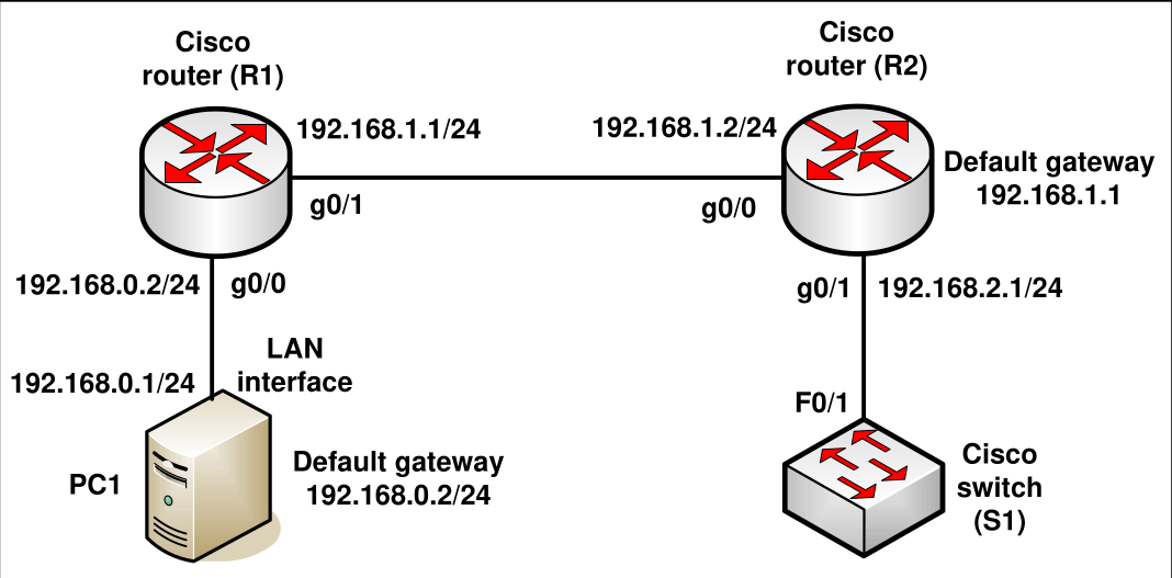
- PC1: Acts as the SNMP Manager. IP:
192.168.0.1/24, Default Gateway:192.168.0.2. - R1 (Cisco Router): Acts as an SNMP Agent. Connects to PC1 via
g0/0(192.168.0.2/24) and to R2 viag0/1(192.168.1.1/24). - R2 (Cisco Router): Acts as an SNMP Agent. Connects to R1 via
g0/0(192.168.1.2/24) and to S1 viag0/1(192.168.2.1/24). Default Gateway:192.168.1.1. - S1 (Cisco Switch): Connects to R2 via
F0/1. Used to simulate link state changes.
Before Begin the lab
- Connect the network equipment of the windows PC, Cisco router, and switch as shown in LAB10 Topology.
- Configure the IP addresses of the PC and routers as shown in the figure.
Part I: Configure SNMP Manager and Agents
In Part I, SNMP management software will be installed and configured on PC1, and R1 and R2 will be configured as SNMP agents.
1. Install an SNMP management program.
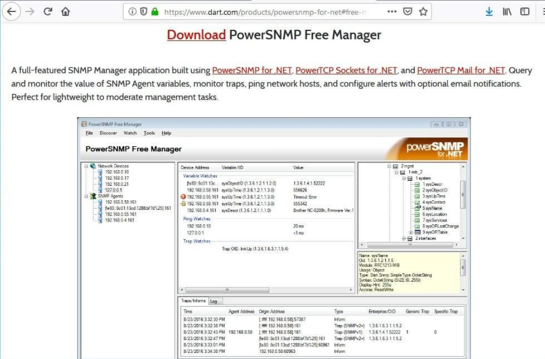
- (a) Download and install the PowerSNMP Free Manager by Dart Communications from https://www.dart.com/products/powersnmp-for-net#free-manager. You can also get a copy from MyLE system.
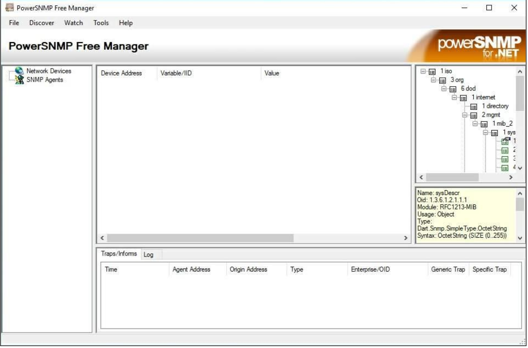
- (b) Launch the PowerSNMP Free Manager program.
- (c.1) Click No if prompted to discover available SNMP agents. You will discover SNMP agents after configuring SNMP on R1.
- (c.2) PowerSNMP Free Manager supports SNMP version 1, 2, and 3. This lab uses SNMPv2.
- (d) In the pop-up Configuration window (if no pop-up window appear, go to Tools > Configuration), set the local IP address to listen on 192.168.0.1, set the port number to listen trap on 162 and click OK.
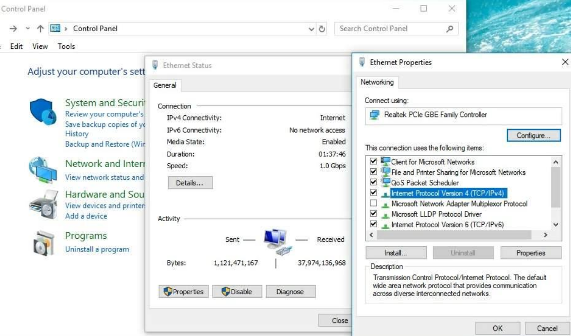
- (e) On PC1, configure the IP address and default gateway as shown in Figure 2.
2. Configure an SNMP agent.
- On R1, enter the following commands from the global configuration mode to configure the router as an SNMP agent.
R1(config)# snmp mib nhrp
R1(config)# snmp-server community networklab ro SNMP_ACL
R1(config)# snmp-server location snmp_manager
R1(config)# snmp-server contact networklab_admin
R1(config)# snmp-server host 192.168.0.1 version 2c networklab
R1(config)# snmp-server enable traps
R1(config)# ip access-list standard SNMP_ACL
R1(config-std-nacl)# permit 192.168.0.1- Note that in line 1 above is for enabling NHRP SNMP agent code.
- In lines 2, the SNMP community string is networklab, with read-only privileges, and the named access list SNMP_ACL defines which hosts are allowed to get SNMP information from R1.
- In lines 3 and 4, the SNMP manager location and contact commands provide descriptive contact information.
- Line 5 specifies the IP address of the host that will receive SNMP notifications, the SNMP version, and the community string.
- Line 6 enables all default SNMP traps, and lines 7 and 8 create the named access list, to control which hosts are permitted to get SNMP information from the router.
- At this point, you may notice that the PowerSNMP Free Manager is receiving notifications from R1. If it is not, you can try to force a SNMP notification to be sent by shutting down R1’s interface. Continue to the next step if it is unsuccessful.
3. Discover SNMP agents.
- From the PowerSNMP Free Manager on PC1, open the Discover > SNMP Agents window. Enter the IP address 192.168.0.255.
- In the same window, click Properties and set the Community to networklab and the SNMP Version to Two, and then click OK.
- Now you can click Find to discover all SNMP agents on the 192.168.0.0 network.
- The PowerSNMP Free Manager should find R1 at 192.168.0.2. Click the checkbox and then Add to add R1 as an SNMP agent.
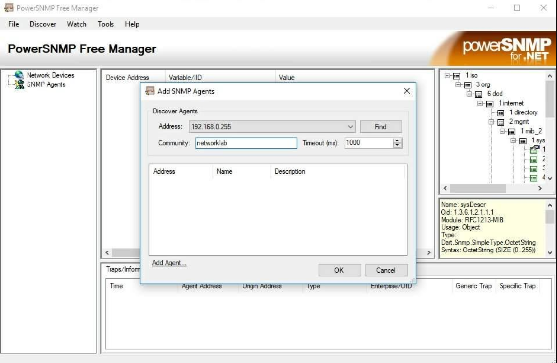
- If R1 is not automatically found, you can add R1 manually by clicking Add Agent in the popup SNMP Agents window, and fill in the following information: Address = 19.168.0.2, Port = 161, Version = 2, Community = networklab.
- In the PowerSNMP Free Manager, you will see that R1 is added to the list of available SNMPv2 agents.
- Configure R2 as an SNMP agent. You can use the same snmp-server commands that you used to configure R1.
- After R2 is configured, add R2 as an SNMP agent using the same process that you used to discover R1.
SNMP Traps
- A trap is a notification mechanism where the occurrence of certain events at an SNMP agent triggers the transmission of an SNMP trap message to an SNMP manager.
- SNMP has several predefined traps that include events when the system is rebooted, an SNMP agent is started, when a link goes up or down, and when an unauthorized access has been attempted.
Part II: Put a Network Interface Down and Convert OID Codes with the Cisco SNMP Object Navigator.
In Part II, you will force SNMP traps to be sent to the SNMP manager located at PC1. You will then convert the received OID codes to names to learn the nature of the messages. The MIB/OID codes can be easily converted using the Cisco SNMP Object Navigator located at http://www.cisco.com.
1. Clear current SNMP messages.
- In the PowerSNMP Free Manager, right-click the Traps window and select Clear to clear the SNMP messages.
2. Generate SNMP traps and notification.
- On R2, enter the following commands from the global configuration mode to put down and up the g0/1 interface.
R2(config)# int g0/1
R2(config)# shutdown
R2(config)# no shutdown- From the PowerSNMP Free Manager on PC1, you will see a number of SNMP trap notifications received in the traps window.
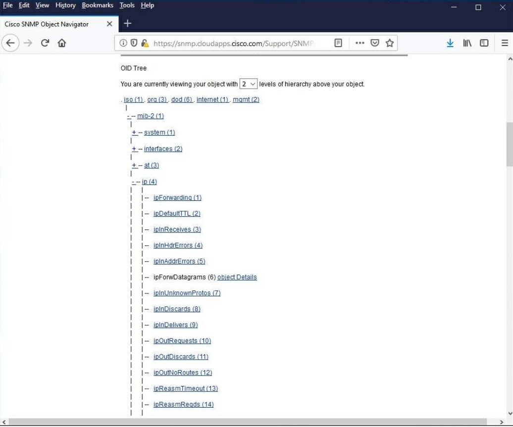
3. Decode SNMP MIB/OID messages.
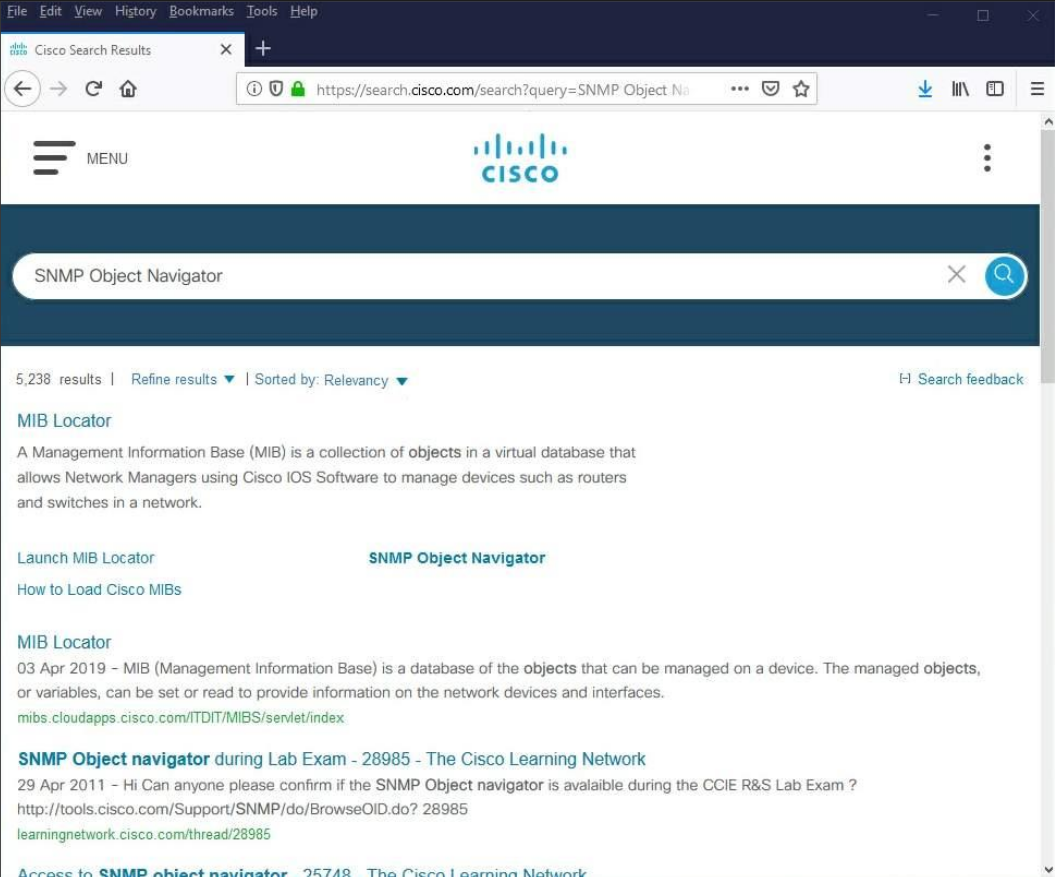
- From a computer with Internet access, open a web browser and go to http://www.cisco.com.
- (a) Using the search tool at the top of the window, search for SNMP Object Navigator.
- (b) Navigate to the MIB Locator page. Click the SNMP Object Navigator. At this stage, you need to create a new account and/or enter your username and password to get an access to the SNMP Object Navigator page
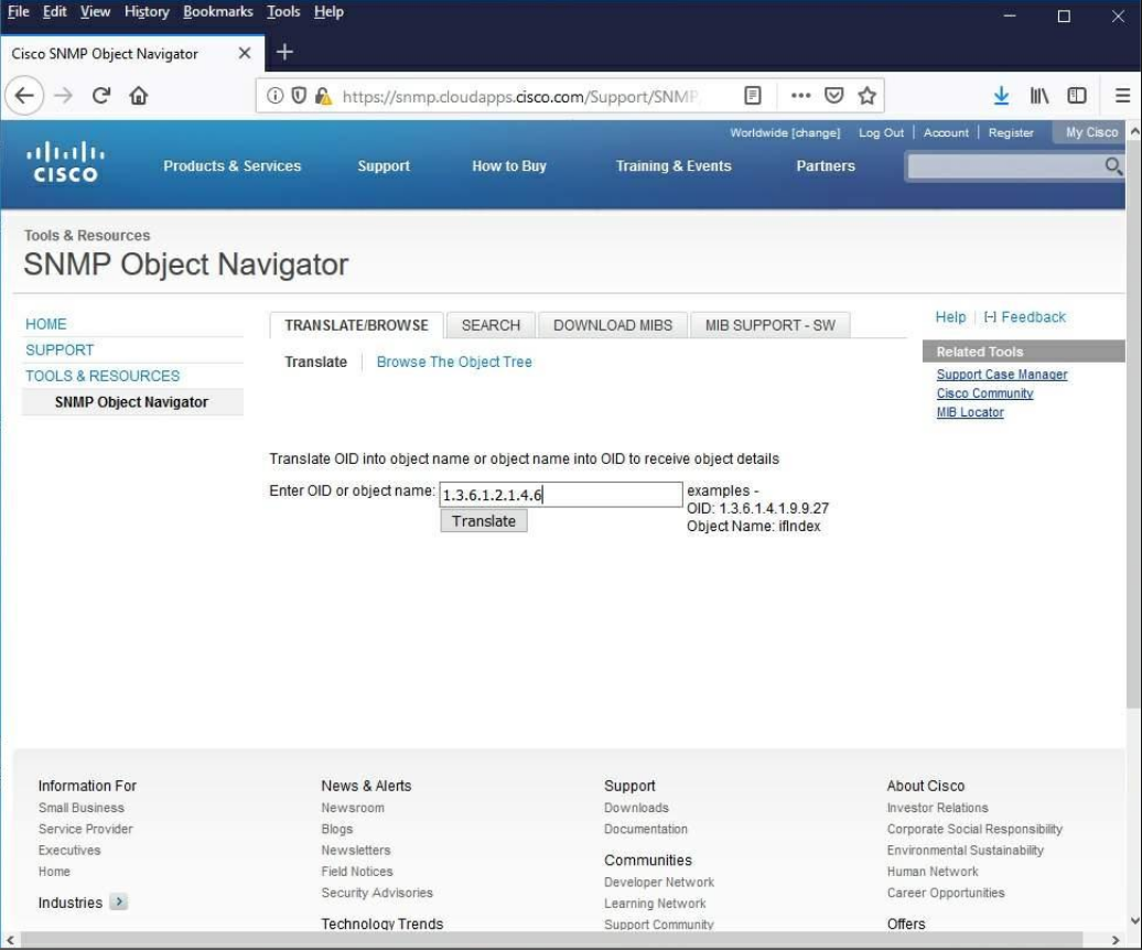
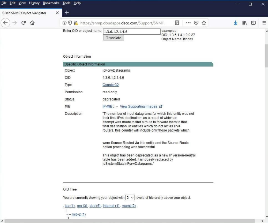
- (c) Using the SNMP Object Navigator page, decode the OID code number from the PowerSNMP Free Manager generated in Step 2. Enter the OID code number and click Translate.
Device-by-Device Lab10 SNMP Procedures
1. PC1 (Windows / SNMP Manager) Procedure
Step 1.1: Connect your PC’s Ethernet port to R1’s g0/0 interface.
Step 1.2: Configure your Windows IPv4 settings with the IP address and default gateway as shown in the topology.
[WAIT FOR STEP 2.2] Wait for R1 to finish configuring its basic IP addresses so your gateway is reachable.
Step 1.3: Download and install the PowerSNMP Free Manager by Dart Communications from https://www.dart.com/products/powersnmp-for-net#free-manager (or from the MyLE system).
Step 1.4: Launch the PowerSNMP Free Manager program.
Step 1.5: Click No if prompted to discover available SNMP agents. (You will discover them manually after R1 is configured). Note that this lab uses SNMPv2.
Step 1.6: In the pop-up Configuration window (if no pop-up appears, go to Tools > Configuration), set the local IP address to listen on 192.168.0.1, set the port number to listen trap on 162 and click OK.
[WAIT FOR STEP 2.3] Wait for R1 to configure its SNMP Agent settings.
Step 1.7: Discover R1. Open the Discover > SNMP Agents window.
- Enter the IP address
192.168.0.255. - Click Properties and set the Community to
networklaband the SNMP Version toTwo, then click OK. - Click Find to discover all SNMP agents on the
192.168.0.0network. The manager should find R1 at192.168.0.2. Click the checkbox and then Add to add R1 as an SNMP agent.
(If R1 is not automatically found, add it manually by clicking Add Agent and filling in: Address = 192.168.0.2, Port = 161, Version = 2, Community = networklab).
[WAIT FOR STEP 3.3] Wait for R2 to configure its basic IP addresses and SNMP Agent settings.
Step 1.8: After R2 is configured, add R2 as an SNMP agent using the exact same process you used to discover R1.
Step 1.9: Prepare for trap capture. Right-click the Traps window in PowerSNMP Free Manager and select Clear to clear any existing SNMP messages.
[WAIT FOR STEP 3.4] Inform R2 that you are ready. Wait for R2 to bounce its network interface.
Step 1.10: You will see a number of SNMP trap notifications arrive in the traps window. Note the OID code numbers.
Step 1.11: Open a web browser and go to http://www.cisco.com.
- Search for “SNMP Object Navigator” and navigate to the MIB Locator page. (Log in or create a free account if required).
- Enter the OID code number you received in the PowerSNMP Free Manager and click Translate to decode the message.
2. R1 (Cisco Router) Procedure
Step 2.1: Connect your g0/0 interface to PC1. Connect your g0/1 interface to R2’s g0/0 interface.
Step 2.2: Configure your basic IP addresses and enable routing:
R1# conf t
R1(config)# interface g0/0
R1(config-if)# ip address 192.168.0.2 255.255.255.0
R1(config-if)# no shutdown
R1(config-if)# interface g0/1
R1(config-if)# ip address 192.168.1.1 255.255.255.0
R1(config-if)# no shutdown
R1(config-if)# exit
R1(config)# ip routing
[WAIT FOR STEP 1.6] Wait for PC1 to install and configure the PowerSNMP Free Manager.
Step 2.3: Configure R1 as an SNMP agent to report to PC1. Enter the following commands:
R1(config)# snmp mib nhrp
R1(config)# snmp-server community networklab ro SNMP_ACL
R1(config)# snmp-server location snmp_manager
R1(config)# snmp-server contact networklab_admin
R1(config)# snmp-server host 192.168.0.1 version 2c networklab
R1(config)# snmp-server enable traps
R1(config)# ip access-list standard SNMP_ACL
R1(config-std-nacl)# permit 192.168.0.1
(At this point, PC1 may start receiving notifications. If PC1 cannot discover R1, try forcing a trap by shutting down and bringing up an interface).
[WAIT FOR STEP 1.11 & 3.4] Stand by while PC1 discovers R1 and R2 sets up its configurations. Your primary active role in this lab is complete.
3. R2 (Cisco Router) Procedure
Step 3.1: Connect your g0/0 interface to R1’s g0/1 interface. Connect your g0/1 interface to S1’s F0/1 interface.
Step 3.2: Configure your basic IP addresses and default routing back to PC1:
R2# conf t
R2(config)# interface g0/0
R2(config-if)# ip address 192.168.1.2 255.255.255.0
R2(config-if)# no shutdown
R2(config-if)# interface g0/1
R2(config-if)# ip address 192.168.2.1 255.255.255.0
R2(config-if)# no shutdown
R2(config-if)# exit
R2(config)# ip route 0.0.0.0 0.0.0.0 192.168.1.1
[WAIT FOR STEP 1.7] Wait for PC1 to successfully discover R1 as an SNMP agent.
Step 3.3: Configure R2 as an SNMP agent (using the same structure as R1, targeting PC1):
R2(config)# snmp mib nhrp
R2(config)# snmp-server community networklab ro SNMP_ACL
R2(config)# snmp-server location snmp_manager
R2(config)# snmp-server contact networklab_admin
R2(config)# snmp-server host 192.168.0.1 version 2c networklab
R2(config)# snmp-server enable traps
R2(config)# ip access-list standard SNMP_ACL
R2(config-std-nacl)# permit 192.168.0.1
R2(config-std-nacl)# exit
[WAIT FOR STEP 1.9] Wait for PC1 to successfully discover R2 and clear its trap window.
Step 3.4: Generate SNMP traps. Enter the following commands to put down and up the g0/1 interface, which will trigger link state traps to PC1.
R2(config)# int g0/1
R2(config-if)# shutdown
R2(config-if)# no shutdown
[WAIT FOR STEP 1.11] Stand by while PC1 decodes the traps you just generated.
4. S1 (Cisco Switch) Procedure
Step 4.1: Connect your F0/1 interface to R2’s g0/1 interface.
Step 4.2: Power on the switch. No internal configuration is required for this lab; it simply serves as an active link partner so R2’s g0/1 interface can transition between “up” and “down” states to generate SNMP traps.